
I recently obtained a U.S. model IBM PC 5150 “Model A” containing a 110/115/120 Volt power supply. I live in the UK where we have a 240V electricity supply, and Ideally I’d like not to have to fuss around with a step down transformer in order to use it on 220/230/240 V, which looks like it’s going to involve a little modification.
There are three main areas we need to look at, as follows:
Main board changes
From studying its schematic, it is clear that the 115V IBM 5150 Power supply is a Flyback converter.
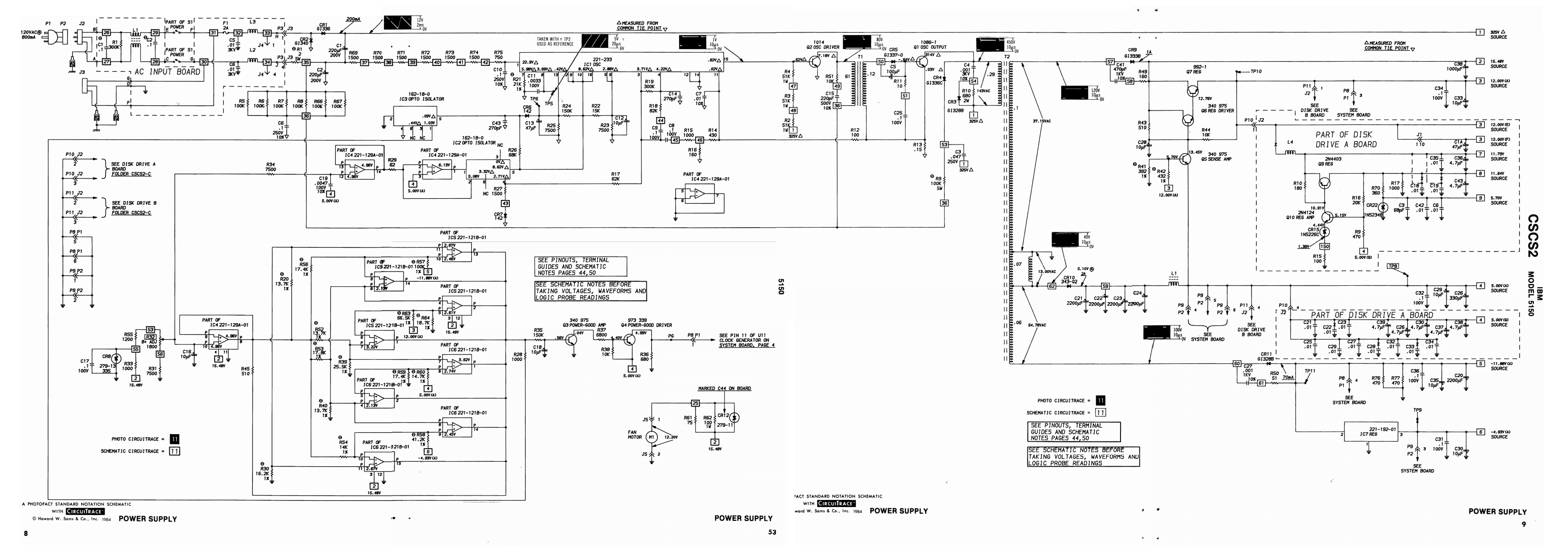
A few variants of this supply exist but the examples I have seen so far are pretty close to this design.
I’m generally pretty reluctant to mess with Flyback power supplies, mostly because I don’t know much about them. In principle they are fairly simple, in practical implementation they are typically laden with details of significant complexity.
The most striking feature of the 5150 PSU’s design, is that with roughly double the number of components, it is substantially more complex than a modern design, which most to me, are darn well complicated enough. Great.
The first thing I notice: Oddly, it is designed with a voltage doubler at the input stage, normally this allows easy switching between 115/230V operation, yet this supply clearly does not have even a fitting option for this.
After some discussion on the Vintage Computer Federation forums, we discover there is a 220V power supply of a very similar design, with which it shares its secondary stage, and many components (including transformers). Unfortunately its primary side is sufficiently different that it is not a good starting point for the modifications we have to make here.
Still, this is good news because it means the supply is already internally operating from +325VDC, which is about what we’re going to end up when we eventually end up replacing the doubler with a full bridge rectifier.
Change 1: Full bridge rectifier + NTC

Above we can see the standard paltry half-bridge rectifier. Time to bring in a more serious solution…
The most obvious change is to remove the voltage doubler, and replace it with a full bridge rectifier. I also replace R1 with an NTC which keeps those inrush currents well below what my replacement bridge (KBPC610) is rated for.
I even took a brief moment to model the inrush current with the NTC:

With a peak of 8A, not anything to lose sleep over.
But it is not going be quite that simple. This is because there are a few gubbins hanging off the junction between C1 and C2, which we’re going to have to deal with first. They were OK with the doubler because they could safely draw current across C2.
Without the doubler, the voltages between C1 and C2 would drift out of balance, eventually resulting in C1 exploding due to overvoltage. This would be highly undesirable given that this is a vintage collector’s item.
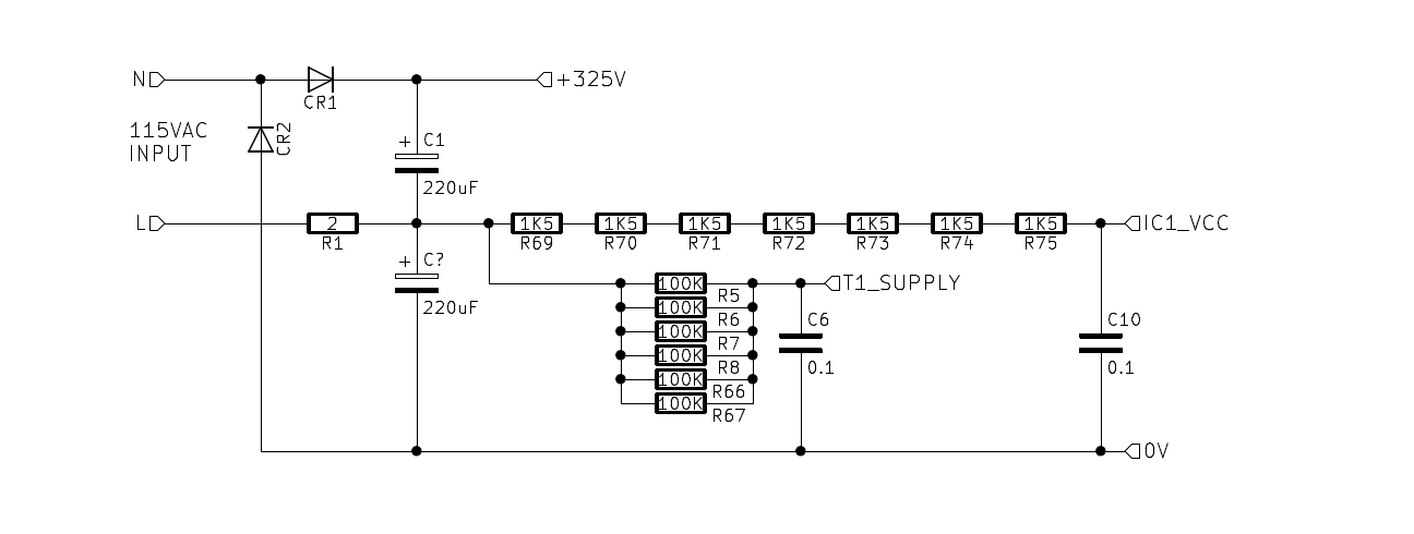
Change 2: R69-R75
Let’s take a look at the first problem, that big long chain of resistors, R69 through R75.

We’re going to have to disconnect it from the 162V centre point, and move it to the 325V supply, which is going to mean changing those resistors.
IC1 (NE5560) is self regulating. It seems to hold about 21.4VDC at VCC, and with the values specified on the schematic, it’d be at about 14mA.
We can work that out as:
(162V - 22.9V) / 9750 (ohm) = 0.014A - 14mA
So assuming that configuration, the new value of that chain would be:
(325V - 22.9V) / 0.014 (14mA) = 21578 (21K5)
It is not quite that on my particular unit, as I have 7x 1.5K resistors in that chain, making a total of 10K5 :
(162V - 22.9V) / 10500 (ohm) = 0.0132A - 13mA
So the new value of that chain should actually be:
(325V - 22.9V) / 0.0132 (13mA) = 22886 (22K8)
Change 3: R5,6,7,8,66,67
Now the second problem, the feed for T1 taken via these resistors:

From experimentation I can see that a total 7-8mA flows through these resistors, with nearly that much again supplied via R9 from the flyback process, which thankfully we don’t have to touch, as that was +325VDC based before, and will be after modification too.
So once again, we’re just going to double the resistance, replacing the 6x 100K resistors with 6x 200K resistors, moving the source from the 162V centre point to the 325V supply in the process.
The voltage at label 36 varies from 1.8 to 10V depending on load, and I have confirmed that this remains the case, including the same 7-8mA passage of current, after changing those resistors.
Change 4: Add 120K 2W Resistors across C1 and C2
Another little change, some 120K 2W resistors across C1 and C2. Belt and braces mostly, keeps the voltages between them stable. Most importantly, avoids the appliance repairman’s favorite side gig – being belted by a sneaky fully-charged smoothing capacitor.
Adding it all together
Combining all of the changes thus far, on the main PCB we are going from this:
To this:

Here’s a couple of shots of the primary side before my modifications:
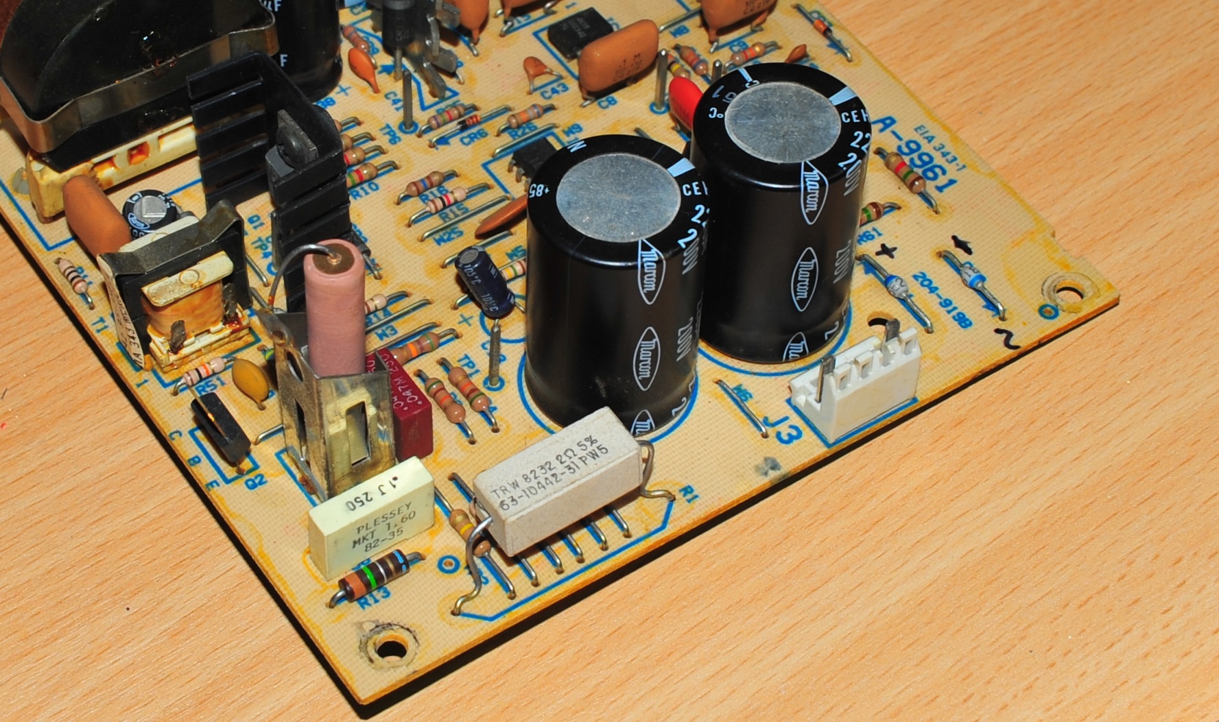
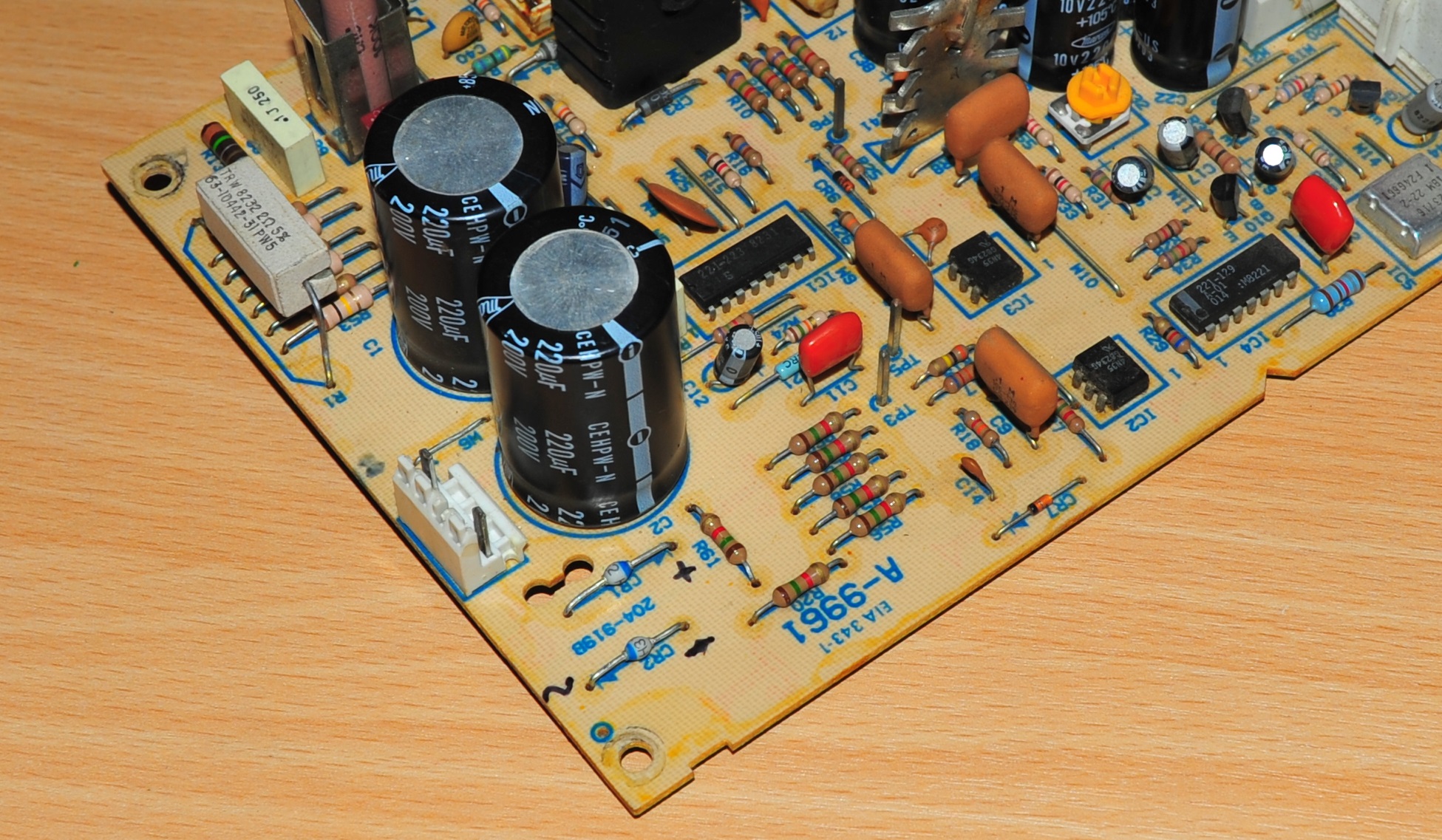
And now here it is with after modification:
 I have used heavy (1.0mm) solid copper wires wrapped in two layers of heatshink tubing for the runs between the bridge and the PCB. Keeps everything mechanically sound!

And the two 120K resistors across C1 and C2. I’ve soldered them directly to the underside of the PCB, leaving a 1mm gap between the PCB and the resistors’ bodies. Just in case.

That’s it for the changes to the main board. Now for the other stuff…
AC Input board changes
Change 1: Replace filter capacitors on AC board

The two 0.1uF capacitors on the AC Board are only 125V rated. They must be replaced with 250V editions. I replaced mine with X1 rated Kemet PHE844RD6100MR30L2’s. Complete overkill but they weren’t too expensive, and with 22.5mm pin spacing went fairly easily in the place of the existing caps.
Change 2: R1 to 560K
This probably isn’t strictly necessary, but I’ve replaced the 300K resistor that was there with 560K 1W resistor.
Changing the AC fan (if fitted)
It is well known that many early units were fitted with 115VAC fans. In the interests of keeping it original, I’ll be replacing it with a 230VAC fan – keeping the old one if it ever needs to be converted back.
It is connected to the AC input board via a 4 position connector resembling a Molex 90331 connector, a rare and obscure item which which I do not know who manufactured, let alone have a part number for. so the original will have to be preserved.
To extract the contacts – I made up a tool, which is the ground down end of a coat hanger:

Molex’s website tells us we can use KK .156 (KK396) contacts with their 90331 connector. They do also fit in this rather nicely, but needed to be crimped fairly thin vertically, in order to fit into the housing.
It is often said that the AC Fan model was a lot quieter than the later DC fan supplies. I myself am undecided if this is actually the case, more of a different sound in my opinion. I would say that the ‘old school’ sounding whine of an AC fan is one I recall from my younger years, and is a feature I’d like to preserve.
The AC fan we seem to find in U.S. model 5150’s (and also 5160’s) is the Rotron “Sprite” SU2C1. It is still manufactured today.
Once upon a time, there was also a 230V version (SU3B1), and I sourced a couple of new old stock units from eBay. This is completely unnecessary, literally me just being a pedant for originality. If you also want to convert to a 230V AC Fan, I would recommend the EBM PAPST 8556N.

The Sprite is a tad quieter, but has almost exactly the same old school whine as the the EBM PAPST.
Note that the Rotron Sprite fan is built backwards, so when replacing with something else, it will have to be mounted the other way around to maintain the original direction of air flow.
Switching it on at 230V
It is all well and good to speculate about the workings of this supply, and make modifications, but it is quite something else to then go and switch it on.
For my initial “switch on”, I connected a 40W light bulb in series, with the supply under no load, briefly pulsing the power, checking the critical voltage / current measurements each time.
These are:
- 50/50 voltage split between C1 and C2 (I got around 150V each initially)
- 21-22V present on Pin 1 of IC1
- 8-2V DC at label 36 of the schematic
- IC1 consuming around 10-12mA current
- 7-8mA combined flowing through R5,6,7,8,66,67
Beyond that, running it for a few hours with about 40W of dummy load was all the testing I did before reconnecting it to my PC.

Shopping list
All of my parts were sourced from Mouser. At the time of writing Farnell UK did not stock any 3K 2W resistors, and the only 3K3 2W resistors were too large to fit in place of what I was removing.
| Description | Quantity | Exact part number used |
| Fan | 1 | EBM PAPST 8556N (or) Comair-Rotron Sprite SU3B1 |
| KK .156 Crimp contacts for fan | 2 | Molex 08-50-0108 |
| 0.1uF X1 (or X2) rated filter capacitors | 2 | Kemet PHE844RD6100MR30L2 |
| 15R NTC | 1 | EPCOS B57237S0150M000 |
| 6A Bridge Rectifier | 1 | Vishay KBPC610 |
| 3K 2W Resistor | 1 | Vishay PR02000203001JR500 |
| 3.3K 2W Resistors | 6 | Vishay PR02000203301JR500 |
| 200K 2W Resistors | 6 | Vishay PR02000202003JR500 |
| 560K 1W Resistor | 1 | Unspecified |
| 120K 2W Resistors | 2 | Unspecified |
Unexpected troubles: Hissing / squealing noise
When I first powered the supply on connected to the PC, I noticed a rather nasty sounding hissing noise coming from the supply.
At first I thought this could have been as a result of my changes, but I did also hear it when attached to a test load with the supply in its original form at 110V.
Interestingly, putting just a little more load on the +12V rail seemed to silence it. Not satisfied with this solution, I spent several evenings investigating. I finally discover the problem when attaching a scope to the +5V rail (Why the heck I didn’t do this up front I do not know!)
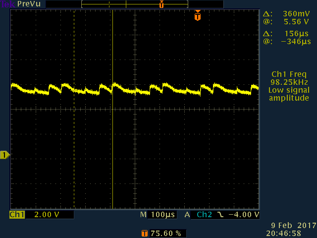
Over time the ESR in the caps on the secondary side had deteriorated, resulting in quite a lot of ripple, which effectively destabilised the regulation control loop, meaning that the supply was constantly changing to and from skip cycle and continuous mode. This constant stopping and starting of the supply happens at a frequency which is audible, and darn annoying.
The solution was to replace all of the capacitors on the secondary side, but while at it, I just replaced all of the electrolytic capacitors.
2 thoughts on “Converting an IBM PC 5150 “Model A” black 115V power supply to 230V”