I’ve been using these displays for 15 years now, but every time, that same old problem comes up: They’re just a bit annoying to interface with.
Despite them being difficult to interface with, HD44780 and compatible clones remain the defacto standard for character LCDs, with no improved replacement in sight.
There are a lot of ‘Backpack’ boards on the market these days which offer an I2C, SPI or even RS232 interface. Although these boards have made interfacing simpler in electrical terms, the software side of things is typically made worse.
The problem
is pretty simple. The HD44780 is a “Motorola bus” peripheral, notable by it having the “E”, and “R/W” signals. They’re only found on 6800 or 68000 derivative microcontrollers.
Strictly speaking, it is only these Motorola processors that can properly interface with an HD44780, for everything else, some kind of fudge is needed.
I’ve personally been endlessly churning out routines to drive these signals under software control, because despite having used scores of different brands of microcontrollers over the years, not one of them has had the magic Motorola bus these displays require.
Recently I found this page which details how to bodge an HD44780 onto an “Intel bus” microcontroller (an AVR in his example).
Let’s have a look at the issue in the simplest possible terms. There are three signals that differ between Intel and Motorola bus, all of which are used by the HD44780.
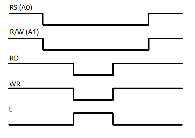
Motorola bus

On Motorola bus, the intention to either read or write to the peripheral is indicated at the same time as the address lines are setup, then, a single signal ‘E’ triggers either the read or write.
Intel bus
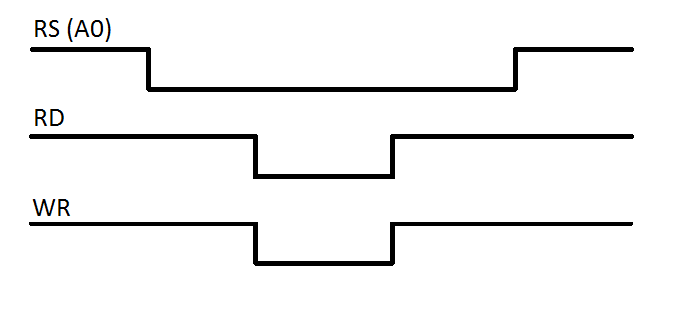 On Intel bus, there is no R/W signal, instead the ‘E’ signal is replaced by two separate read and write signals.
On both a Motorola and Intel system, the RS signal can be connected to the least significant address line (A0), but when it comes to the read and write, we have a slight problem. By the time we know whether or not the CPU is going to read or write, it’s too late, and no, we can’t just deliver the R/W signal at the same time as ‘E’ because, that’s violation of the timing requirements.
We’re left with the unsolvable problem of not having a replacement for R/W. So that’s it. It’s impossible to directly translate Intel bus to Motorola bus.
Solutions
Because the HD44780 only has one address line, there’s a simple bodge which offers an acceptable solution to this problem:
Here, we’ve used an extra address line to drive R/W, and RD and WR are NAND’d into E.
This means the HD44780’s two registers end up with four addresses, two read, and two write. It’s not a direct conversion, but at a pinch, I’ll take it.
Why go to all this all this effort?
For the most part, yes, this is extra hassle to connect a character LCD, but let’s look at the difference this makes to the software.
Before
This is an example of the minimum code which writes a character to the display using the most common ‘bit bang’ mode. This was taken from my 8OD project, which originally was demonstrated using an HD44780 with this method.
void lcd_data(uint8_t data)
{
    lcd_setrs(1);
    lcd_byte(data);
    lcd_strobe(D_43uS);
}

void lcd_byte(uint8_t byte)
{
    outp(PORTD, 0x00FF, byte);
}

void lcd_setrs(int on)
{
    if (on)
        outp(PORTD, 0x400, 0x400);
    else
        outp(PORTD, 0x400, 0x0);

    delay_ncycles(1);
}

void lcd_strobe(uint8_t delay)
{
    outp(PORTD, 0x100, 0x100);
    delay_ncycles(1);
    outp(PORTD, 0x100, 0x0);

    switch (delay)
    {
        case D_1_53mS:
            delay_ncycles(833);
            break;
        case D_39uS:
            delay_ncycles(20);
            break;
        case D_43uS:
            delay_ncycles(23);
            break;
    }
}
That’s an awful lot of fud just to write a single byte.
After
Let’s have a look at the code needed to do the same thing when the HD44780 is memory mapped – attached to the processor bus.
void lcd_data(uint8_t data)
{
    outp(LCD_DATA, data);
    while (inp(LCD_CMD) & CMD_BUSY);
}
Blimey. After attaching the LCD properly, all of that is reduced to 2 lines of code, and depending on the platform and implementation, orders of magnitude better performing. We no longer need any software delays, not even for initialisation. Bus timings are now all native, and we can poll the ‘Busy’ bit on the HD44780 for everything else.
8OD Specific Solution
The board I’m currently doing this work on is 8OD, based on the Intel 8086. Fortunately I’ve got a honking big CPLD on this board, allowing me to experiment with glue logic.
As an added bonus, the 8086 has a signal which directly replaces R/W: DT/R. DT/R is intended for driving bus transceivers but happens to provide the missing timings needed to generate a perfect R/W signal.

Pretty quickly, I whipped up a VHDL module which ties together all of this logic, into a perfect Intel to Motorola bus converter.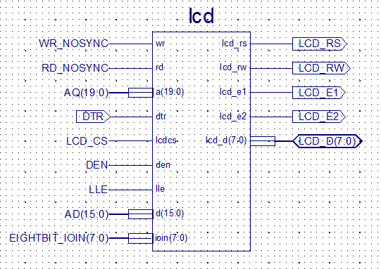
After 15 years of using HD44780’s, this is the first time I’ve ever seen one memory mapped.
Posted in Vintage microcontrollers