As many have said, when embarking on a project, it’s always the smallest details that kick your arse, and today, I’ve hit one of those.
A while back, still mourning the loss of the Intel Desktop Board line, I purchased a Jetway NF9E-Q77 as the Intel DQ77KB had become unobtainable, but this Jetway board, despite being sold as an industrial board, seems to be missing one of the most obvious features you’d expect from an industrial board: Auto power on. I’m rather baffled by this, further by the assertion of use for digital signage, if one of these ends up driving a large display high above the ground, does someone have to reach up to it with a long pole to press the power button every morning?
My first attempt at resolving this was to connect the +PWR_ON (power button) to the boards +5V supply (via a 4.7K resistor), this works good, because when the board is off, +5V is 0v, which is the same as pressing the power button, which just connects +PWR_ON to GND. As luck would have it, it powers on during the falling edge so it works a treat. Problem is – I couldn’t turn the darn thing off, because after shut down it goes right ahead and turns its self back on again, as you’d expect. Not exactly the behaviour I wanted.
Second bodge: This seems to be a common trick, attaching some kind of capacitor across the power switch. This works too. Most of the time…
Given that I want to be able to shut this machine down, and require that it always turns back on when AC power is connected, to heck with it, I’m going to have to use some kind of Microcontroller.
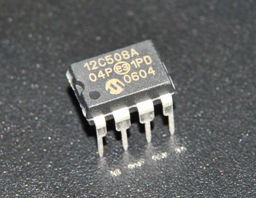
A while back I bought this little relic from a high street electronics retailer (Maplin). I went in there to buy the modern (and common) 12F675, but came out with a 12C508. Was it that they were out of 12F675’s, or perhaps they gave me the wrong part? I don’t know for sure, but I doubt it. Most likely is that my mind was harping back to the bygone era of EPROM PICs, and I really did ask for it.
I find it interesting that high street retailer sells something like this, because this line of PICs is really quite difficult to work with, and is the last thing that the average walk-in-off-the-street hobbyist would ever want to tangle with:
- It requires specialist kit to download code onto it, i.e the £1000+ MPLAB PM3, or a high voltage benchtop EPROM programmer
- It’s OTP (One Time Programmable) so unless you’ve got a whole tube of them (who does right?) there’s only one chance to get the code right
- It uses Microchips’ most basic 12-bit instruction set, for which, C compilers don’t support, so it’s got to be programmed with the dreaded PIC12 ASM language
So what am I going to do here? Cop out and use a 12F675, or conquer one of these once again. Not having written any ASM for many years, I can already see what should be a 1 hour task turning into a 6 hour curiosity project.
In order to make absolutely certain that the machine is turned on in all cases, I decided to make it work like this:
- +5v Standby voltage powers up PIC
- PIC waits 3 seconds
- PIC tests if machine is on (by sampling +5V main supply)
- If powered on, go to step 7
- If not, PIC presses power button for 500ms
- Go to step 2
- Do nothing until powered off and on again
The device would only need 4 connections:
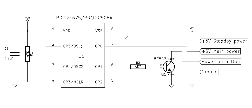
- The +5V standby voltage, which pin 9 on an ATX power supply cable, failing that, most mainboards will have it available on at least one connector, in my case I found it on the CIR header.
- The main +5V. This is found just about anywhere, and is used only to test if the PC is on.
- The power on button active signal. This is either pin 8 or 6 on the front panel header, One of those two is connected to ground, ignore that one and connect the other to this device. It’s no problem to leave the physical power button connected, this device will not interfere with its operation.
- Ground. Take your pick where to connect this.
If using an Intel Desktop Board, or one that is designed to be compatible, the Custom Solutions Header has all four of these connections.
And here’s the source code (download project). Understanding that few would be equipped and comfortable attempting this on an OTP PIC, It also works on PIC12F675 when use12f675 is set to 1.
use12f675 equ 0

if use12f675 == 1

#include "p12f675.inc"
processor 12f675
list f=inhx8m
__config (_INTRC_OSC_NOCLKOUT & _MCLRE_ON & _WDT_OFF & _CP_OFF & _CPD_OFF & _BODEN_OFF)

delay_ms_arg equ 0x20
delay_s_arg equ 0x21
add_arg equ 0x22

else

#include "p12c508a.inc"

processor 12c508a
list f=inhx8m
__config (_IntRC_OSC & _MCLRE_ON & _WDT_OFF & _CP_OFF)

delay_ms_arg equ 0x07
delay_s_arg equ 0x08
add_arg equ 0x09

endif

; Start of code

org 0x00 ; reset vector
goto main

delay_ms
movf delay_ms_arg, f
btfss STATUS, Z
goto outer_loop
retlw 0
outer_loop
movlw 0xF9
movf add_arg, w
inner_loop
movlw 0xFF
addwf add_arg, f
btfss STATUS, Z
goto inner_loop
nop
decfsz delay_ms_arg, F
goto outer_loop
retlw 0

delay_s
movlw 0xFA
movwf delay_ms_arg
call delay_ms
movlw 0xFA
movwf delay_ms_arg
call delay_ms
movlw 0xFA
movwf delay_ms_arg
call delay_ms
movlw 0xFA
movwf delay_ms_arg
call delay_ms
decfsz delay_s_arg, f
goto delay_s
retlw 0

main
movlw 0x00
movwf GPIO

movlw 0x3D
if use12f675 == 1

; 12F675
bsf STATUS, RP0 ; select register bank 1

movwf TRISIO

movlw 0x00 ; All A/D off
movwf ANSEL

bcf STATUS, RP0 ; select register bank 0

movlw 0x07 ; Comparators disconnected
movwf CMCON
else

; 12C508A
tris GPIO
endif

main_loop ; Power button pressing loop

movlw 0x03 ; 3 Seconds per pass
movwf delay_s_arg
call delay_s

btfsc GPIO, 0 ; System now on? Exit if so
goto infinite_loop

bsf GPIO, 1 ; Assert power button

movlw 0xFA ; 250ms delay
movwf delay_ms_arg
call delay_ms

movlw 0xFA ; 250ms delay
movwf delay_ms_arg
call delay_ms

bcf GPIO, 1 ; De assert power button

goto main_loop

infinite_loop ; Done till next power on
goto infinite_loop
Posted in Circuit snippets