Recently while assisting with an Arduino project, I found myself needing a simple circuit which generates either a 1 KHz or or 100 Hz square wave. The reason for this was to connect to an interrupt pin to generate a timekeeping-level accurate 1ms or 10ms timestamp, which the Arduino its self cannot generate as its crystal is fixed at 16.000 MHz
This turns out to be a little more difficult than I expected. Because you can’t divide 100 down to 10 with flip-flops, whatever you end up building is going to do one frequency or the other, requiring a change in crystal to switch. So first of all, let’s look at which crystals can generate these frequencies:
1 KHz
A crystal that can divide down to 1 KHz must be a power of two, multiplied by 1000. Some examples (all of which are easy to come by) are:
- 32.000 KHz (divide by 32)
- 2.048 MHz (divide by 2048)
- 4.096 MHz (divide by 4096)
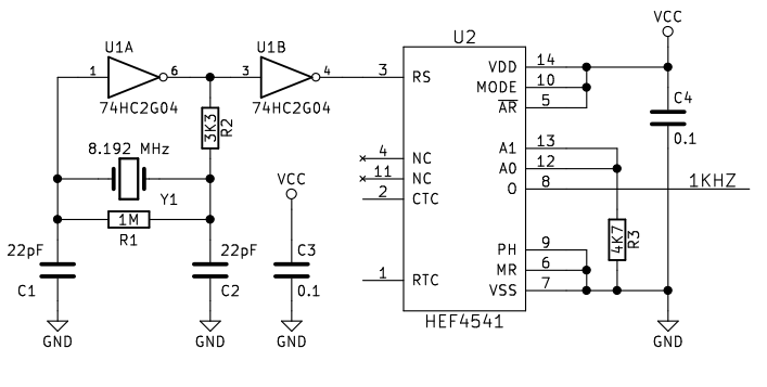
- 8.192 MHz (divide by 8192)
100 Hz
Likewise, a crystal that can divide down to 100 Hz must be a power of two multiplied by 100. These are not so common. Some examples I could find:
- 25.600 KHz (divide by 256) – I could only find one example from a single manufacturer, which is stocked by some vendors but no longer in production
- 1.6384 MHz (divide by 16384) – Once existed, but at the time of writing none appear to be in production or for sale
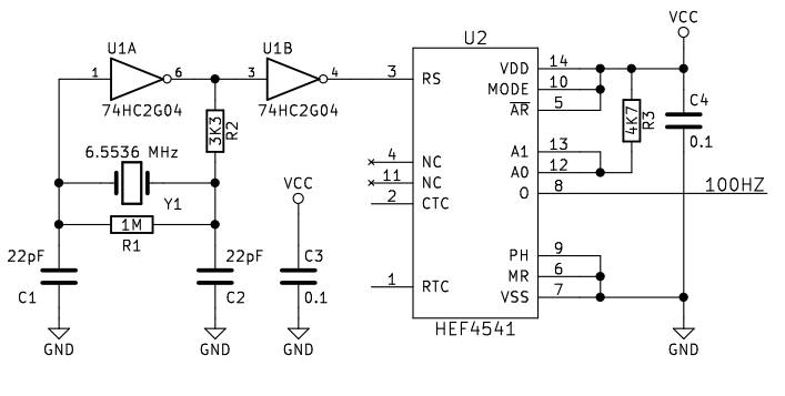
- 6.5536 MHz (divide by 65536) – Several examples in production at the time of writing, reasonably obtainable
My requirements are:
- Must be easy to change from 100 Hz to 1 KHz
- No expensive or obscure components
- Must be all SMT
- Vcc = 5V
The next headache
Now I have to find an IC which can divide two of the above frequencies down to 100 Hz or 1 KHz. The trusty old CD4060 immediately jumps out. If we switch between 25.600 KHz and 32.000 KHz crystals, also changing the output stage – we’ve got a solution. Problem is, this solution falls foul of two my objectives – that one-and-only obscure 25.600 KHz crystal, which is not SMT.
With the only practical primary clock (for me) for 100 Hz operation being 6.5536 MHz, that rules pretty much all CD4xxx timers, which according to their datasheets, can’t operate with such high input clocks.
So far as I could see that leaves two options: 74xx292 (Rare in SMT) and HEF4541. If we are to select 8.192 MHz for the 1 KHz option, both can divide by 8192 and 65536, and handle those input clocks.
One more bump in the road
Because of the obscurity of 74xx292 in SMT, I’ve gone for HEF4541. The HEF4541 can in theory have a crystal connected directly to it, but after hours of profanities I discover that running at Vcc = 5V it can’t quite self oscillate at 6-8 MHz. We can prove this by shorting RS and RTC, and we see that it self-oscillates (with no other components) at about 5.9 MHz, which reveals the shortest propagation time between those two pins.
Great, so now we need another IC. Fortunately that only needs to be a 74HC2G04 which is tiny and inexpensive, barely increasing the footprint of this circuit.
The final solution
First, the 100 Hz version. Note that R3 can also be a wire link.
And now the 1 KHz version. R3 is moved, and the crystal frequency is changed.
A 1 MHz oscillator has a time resolution of 1 µs, why not count 500 cycles and then toggle the output – giving a 1 ms/1KHz square wave. For 100 Hz, count 5000 cycles.
If there is an easy and inexpensive way of doing this, it would be most helpful if you could make mention of it.
Can’t you use a counter to divide the 1khz to 100hz? I would have thought that would be available in smd.
If you find such a thing – do tell
use your oscillator circuit with 1Mhz crystal and use 2 – 74hc390 dual decade counter, to get your desired frequency at the Qd output of the second chip
.Surface mount and DIP-N packages available
I am a beginner. Don’t mind my naive question but why using two 555 timers in ‘Astable mode’ with respective required frequencies of 100Hz and 1kHz set with external R and C, is not an option?
It is an option, however the point of this is that it’s crystal clocked and therefore accurate for timekeeping. The purpose of this circuit is for generating external timer interrupts for microcontrollers.
Thanks for the reply. Appreciate it.